 |
| CV | DESIGN | ART | AUDIO | CONTACT |
|
Amplifier circuit and tube datasheets
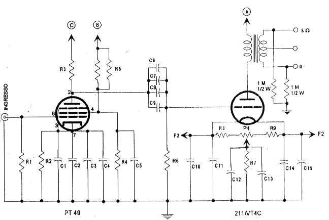
ELECTRIC CIRCUIT OF THE AMPLIFIER SECTION (single channel)
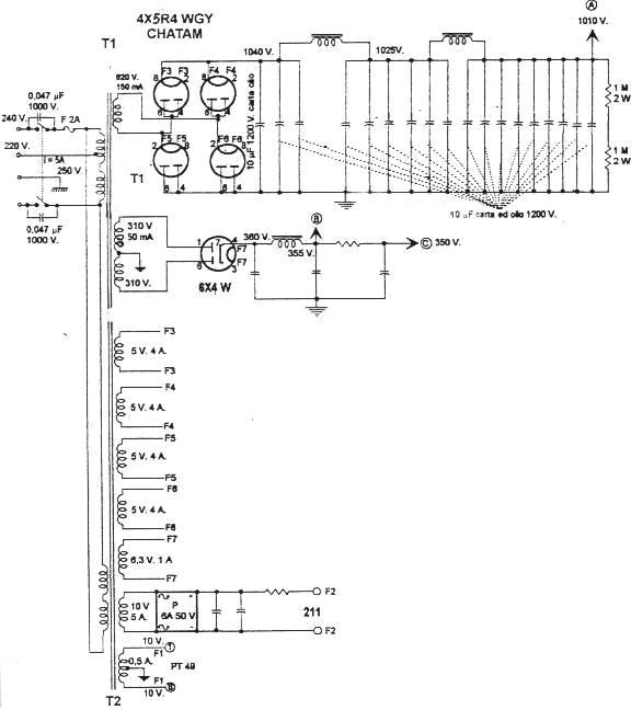
ELECTRIC CIRCUIT OF THE SUPPLY SECTION (single channel)
With the kind permission by AUDION (an old famous Italian hi-fi magazine) I have published the circuit, obviously without the components values, for whose I suggest to read the N. 9 of the same magazine. Particularly thanks to the Director of AUDION, Mr Luciano Macrì, with whom I had some productive opinion exchanges. Our first exchange began at the Electronic Fair in Piacenza some years ago and we are still in contact nowdays. Last time I met him was a few days ago on occasion of the TOP AUDIO 2000 in Milan. Mister Macrì has been one of the first persons with a certain level of culture in the field of the High Fidelity I had ever met and, when in Piacenza I reported to him my intention to build by myself a tube amplifier and to start with a 211, he told me that they always say in these occasions (...and God knows if it was not in this way!): "...but, you start with a tube that needs 1000Vac of anodic voltage? That is extremely dangerous!!". But from the moment I had into my hand a 211 for the first time, into the Lab of eng. Giacomo Pruzzo in Genova, I could not forget it. There are 36 filter capacitors Paper&Oil for the 211 anodic voltage. I then met Mister Stefano Bevacqua, with whom I have done long chats by phone learning much more from him than by the reading of many manuals. Stefano not only sent to me the 36 capacitors (for a full weight of 35 Kg!!), but he followed me in the main steps of the building iter and when, after one year, I finished the assembly and the wiring it was a great satisfaction also for him to know that it was working fine, given that the published circuit on AUDION belongs to him! However my design has some little changes from the original, as follows: 1) I used only one high quality coupling capacitor between the main and the final one (the famous ICAR SP-25 by 1µF - 1000V), rather than two C&O in parallel bypassed with the same number by silver mica, moreover I noted that the bypass by silver mica works in a strange way by high frequency, at least into my system! And not only in that position, infact I tried to bypass also other capacitors into the amplifier section, with less satisfying results, according to what I succeed in hearing with my loudspeakers of middle efficiency (92dB). 2) Then I moved the transformer T2, mantaining in T1 only the high voltages for the 211 in order to have the chance of changing T1, in a second time, with a transformer having a secondary different and to be able to carry the 211 to a different working point). 2.1) Infact, after having finished the plan and after having measured anodic of 211, I had "only" 950V instead of the 1010V previewed. At first, thinking that the reason was some too old rectifiers (5R4WGY CHATAAM). I bought other 8 rectifiers NOS from one of the best Italian stores for fuses (paying the sum of 250 €). But after connecting the new tubes (dated 1952) ...also 950V. Well! But, they were not the rectifiers to make down the voltage, but the big resistance having to the output of the feeding (due to bigger length of the track of the signal given the big amount of the capacitors, different from those of original plan). And so, the idea to have in T1 only the secondary one for the anodic of the 211, has been useful because in future I would have been able to substitute it with a transformer having a bigger secondary voltage, spending a lesser sum of money. 3) I increased the value of the filter inductors (six for both channels), in order to have a lower ripple (obviously, against the impedance to the resonance of the filter). 4) I modified the values and the number of the filter capacitors of the PT49 anodic voltage. 5) I used some values of the resistors different from the original, for the filament of the 211, so to have 9,8V ±0.2V (however after 1h of temperature stabilization, there is a stable voltage of 9,8V). 5.1) I added a resistor (in this case it was 18 Ohm) even for the filament of the PT49, to limit the voltage and to warrant a longer life to the tube. 5.2) However the filaments resistors must be arranged every time through a test. It is not possible to fix the right value (due to voltage tolerances mainly due to the transformer secondary, then for the tube resistances). It is better to insert a calculated value firstly and later measure it, in order to recalibrate.
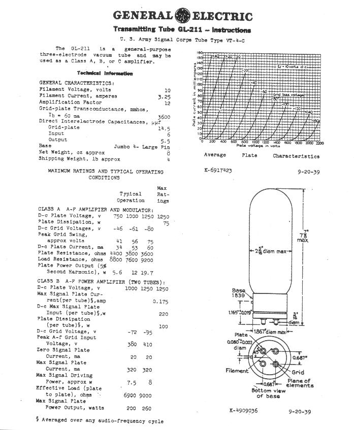
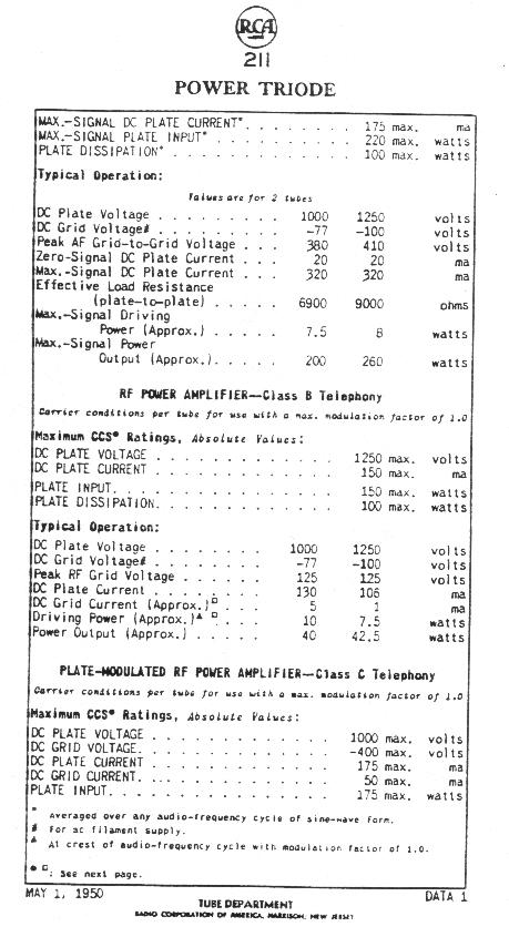
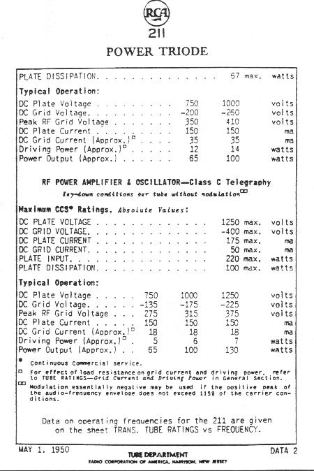
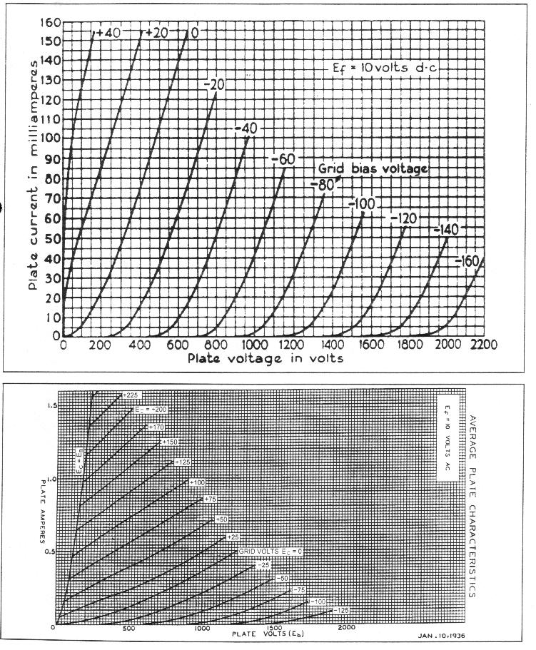
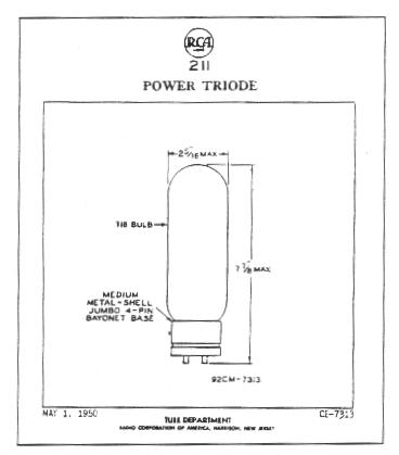
USED TUBES: 211/VT4C General Electric
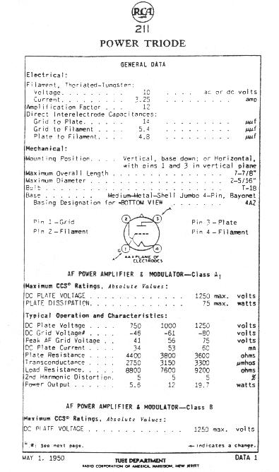
211/VT4C RCA
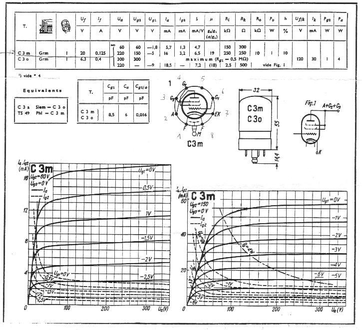
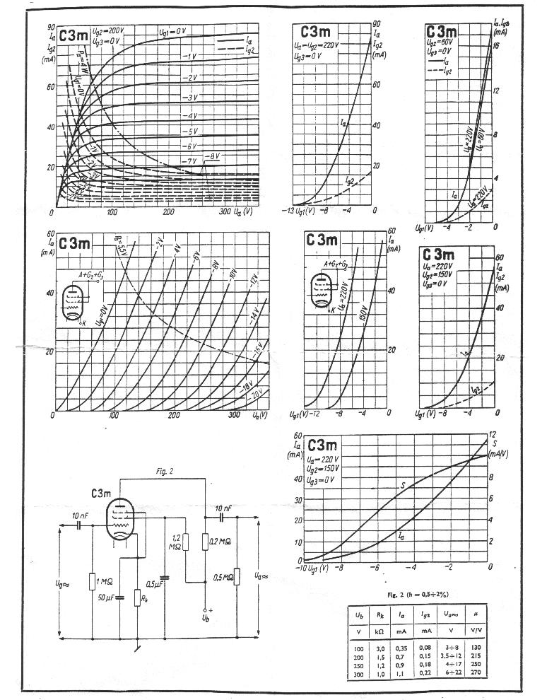
PT49
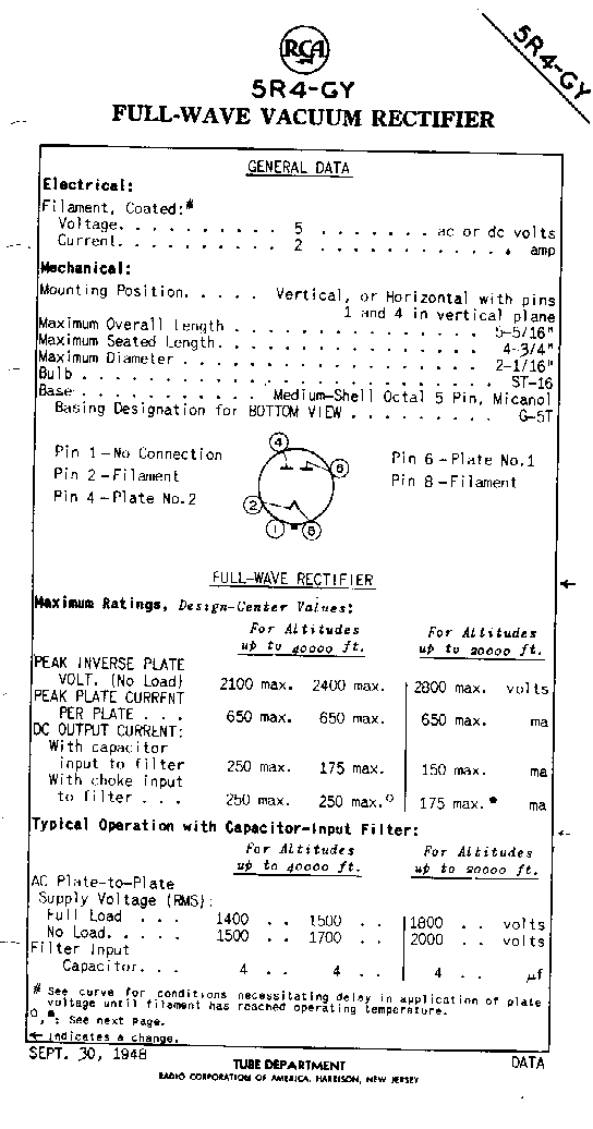
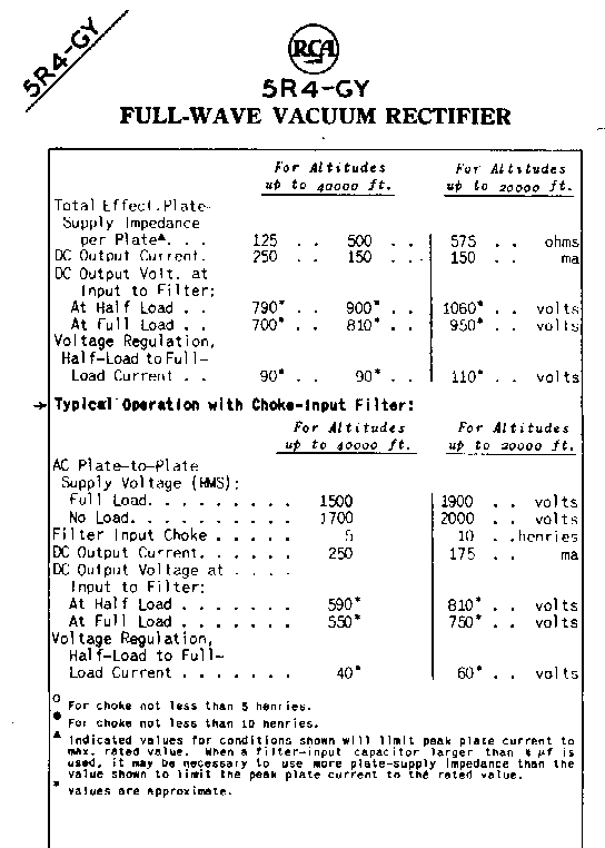
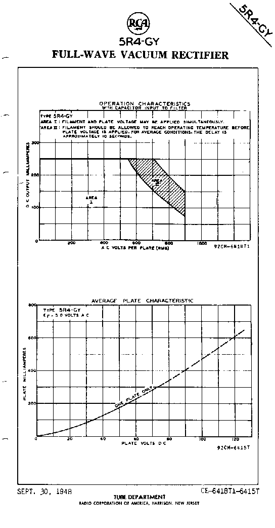
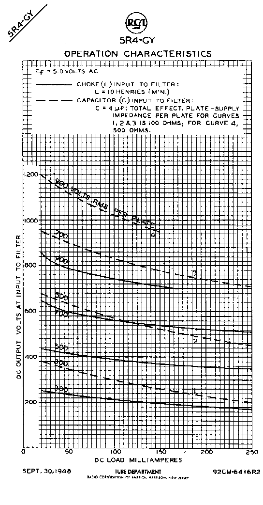
5R4WGY CHATAAM
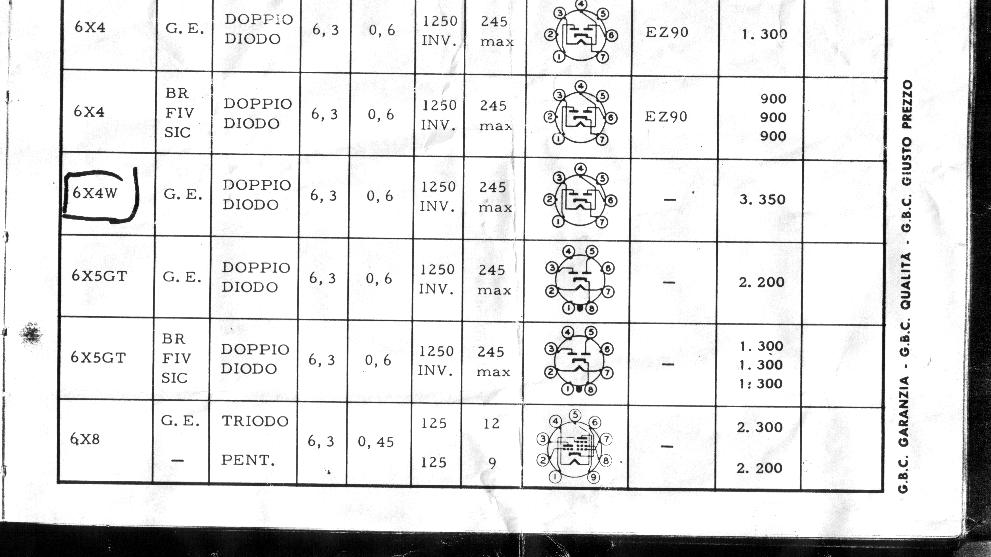
6X4W
|
|
