 |
|
|
CV | DESIGN | ART | AUDIO | CONTACT |
|
A coffee grinder design
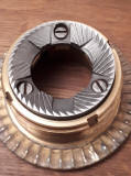
This project was born around an old grinder motor, the aim is to improve and to make some experiments about the precision of grinding coffee, in order to perfectly adapting coffee graininess to my expresso machine. The motor belongs to a very old (mid 1980s) Gaggia MDF grinder I recovered from scrap, but it had a great emotional importance for me, so... disassembling the motor from the MDF body, it appears as the following images
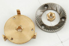
After repairing the motor, cleaning and changing grinder blades
I designed a first version of the V1 grinder to test asap the behavior of the grinded coffee. The new features are constituted by a new fine tune mechanical calibration of the fixing method for setting grains size.
The design is minimalist and all the main parts have been realized in inox 316 to ensure stiffness and high mass to the basic structure and also for the correct degree of hygiene requested for kitchen materials.
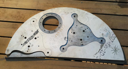
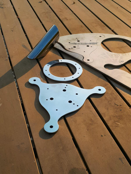
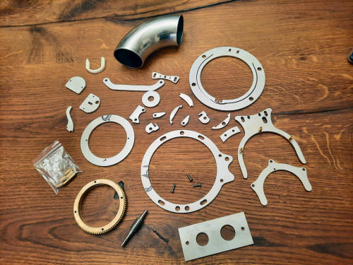
After laser cutting an inox plate of 5mm thickness, obtaining some parts
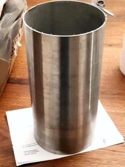
and an inox 316 tube for the body:
and after mirror finishing hand polishing inox pieces
Buying and cutting some further pieces
now I am ready to mount the grinder
The V1 has been designed to collect grinded coffee in a container to have it available for a couple of days. After some tests, I am ready to design the second coffee grinder version. For the V2 I want to grind coffee
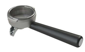
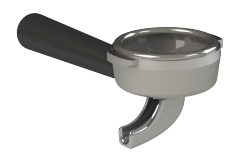
directly in my portafilter to have one fresh material for each extraction, who passionate for coffee knows very well the difference. As all professional expresso coffee machines using Faema E61 brewing unit, mine has two kinds of portafilters
one for the single and another one for the double extraction. So, new V2 grinder must automatically recognize if I am using the single or the double portafilter, starting to grind and driving the proper coffee quantity, without touching any button or any other setting. Another target is given by the coffee distribution inside the portafilter. The current V1 pipe doesn't suit for this purpose, so first of all I have to change the V1 straight pipe from which the grinded coffee comes out to adapt coffee particles distribution inside the portafilter. A granular mixture modify its distribution when agitated and keeping under control the involved variables (mass, particle size, frequency, time, gravity, speed, etc) is possible to remove low density areas in the puck, improving coffee extraction. It is possible to go into detail about density, distribution or coffee grain size reading some interesting publications such as ref1 or ref2 and their references. They provide very useful information for the right values to use in simulations. After some measurements of coffee speed and average particles size/mass that come out from the motor. Putting these variables in a FEA simulation is possible to see particles trajectories on the portafilter, improving distribution applying some small modifications
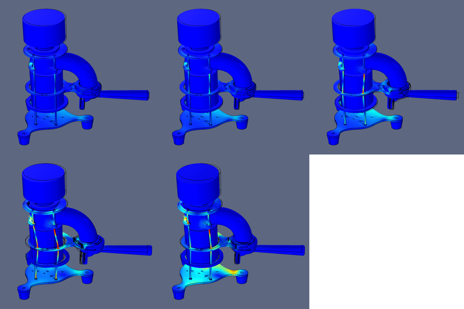
Then, measuring the motor vibration frequency range and acceleration, different aspects on vibrations considereration for structure stress and masses distribution and some other mechanical regulations have been analyzed. The following FEA simulation shows von Mises stress and displacement direction of vibrations around frequencies generated by the motor and propagating through the structure
Maximum vibrations amplitude is focused in some sections of the structure and other parts are fixed and solid like the base. Paying attention that the target is not to eliminate vibrations, on the contrary as we know vibrations are necessary for grains distribution, for this purpose specific VDT (Vibration Distribution Tools) are available on the market and are usually used to aid an uniform particles distribution within the portafilter. Don't forget that vibrations are also useful to move coffee beans each others, allow them to drop gradually, without temporary interruptions. So, for the V2 grinder I added a vibration distribution function using its own vibrations, trying to obtain two accesories in one (obviously using only limited frequencies and amplitudes generated by the motor). Measuring vibrations using an accelerometer on the XY plane on top of the grinder, we can see the frequency range have a great amount of energy between 13 Hz and 120 Hz, with a peak around 20 Hz on both X and Y and a peak at about 100Hz on Y direction (red).
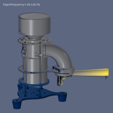
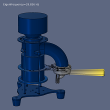
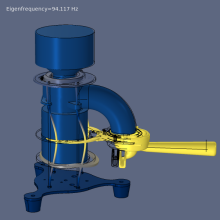
It is interesting to see the Eigenfrequency non linear simulation shows first three structural modes are 18.1 Hz, 29.8 Hz, 94.1 Hz.
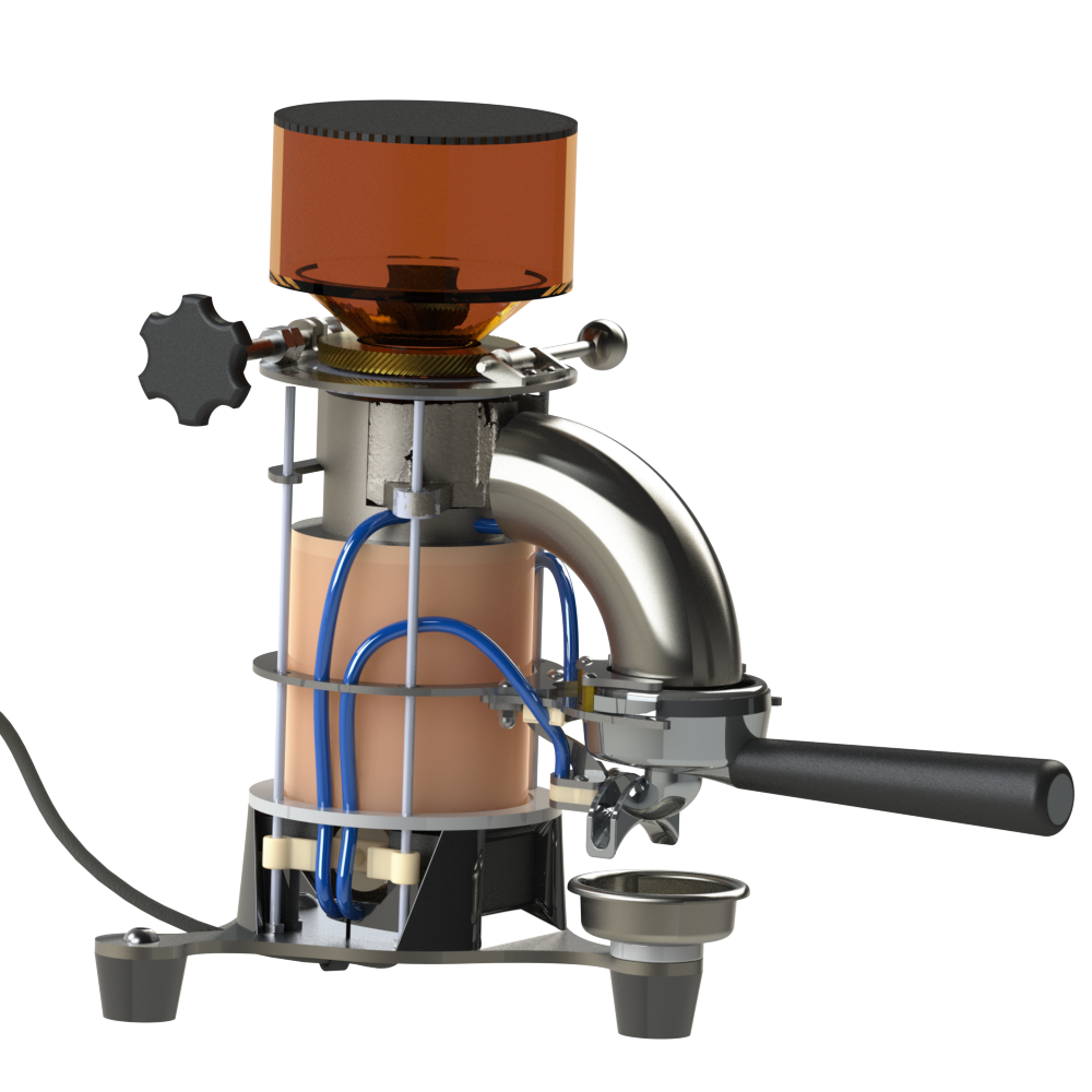
Regarding the displacement direction, the resonance frequency (fundamental mode at 18.1 Hz) with 94.1 Hz are the most interesting frequencies I can work with for coffee distribution. Working on structural parameters, such as materials stiffness or the height regulation of the motor and some other masses (they are free to move in Z direction, because the entire body is fixed along 4 screw bars) I can control and fine tune the vibration range and amplitude, using the most excited frequencies of the grinder vibration modes. After these settings, now I am ready to finalyze the new V2 design of my coffee grinder and order all remaining parts. For the V2 I decided for a naked design as showed here
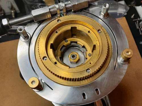
after receiving some new pieces from my laser cutting supplier the rectangular panel on the bottom side of the upper photo is destined to the water filter project, all the other parts after the mirror polishing will be soldered/assembled to start building the new grinder. On V2 I've added also an helical gear transmission and a spring system which blocks grinder blades after any modification to change the desired grain size.
The gear 1:90 transmission permits a more precise fine tuning of coffee grains size, while the blocking system permits to fix the two blades ensuring always the same planarity and position during their work.
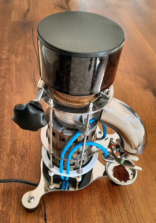
other images of the realized grinder
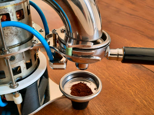
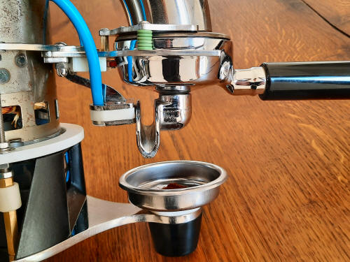
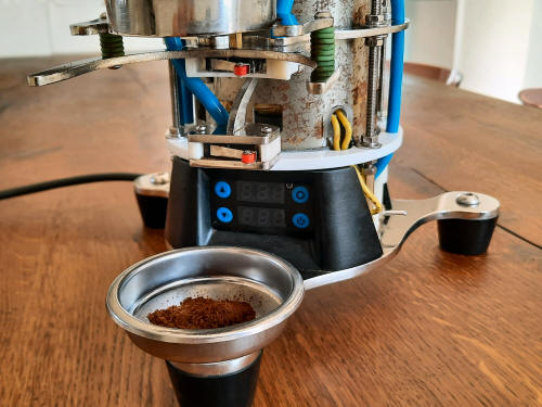
To collect coffee particles, could exit from the channel after the grinder work, I use the blind filter supplied with the other filters of my expresso machine. It is perfect as a powder collector and it is aligned with the grinder essential design.
I don't want to fix the powder collector, but it's necessary to avoid it falls due to vibrations or to accidental impacts. Anyway I want an easy way to use it and a fast method to pick and place it. The fastest method we can use, I think, for this application is the magnetic attraction using magnetic field generated by a permanent magnet. The key is to obtain a force between 10 N and 20 N required to keep in place the blind filter, also in this case a finite element analysis simulation can help to define the problem. In the bottom image it is showed the simulated design, with the coffee powder collector (the iron blind filter) some magnets and one iron screw to increase magnetic surface and focusing flux lines in the center of symmetry.
The magnets are incorporated in a disc which material is transparent to magnetic interactions, for the same reason also the rubber foot is transparent in the above image. This is the simulation result showing magnetic flux streamlines starting from one of the magnets poles and closing to the other one.
Magnetic flux involves the powder collector (passing through it on yellow section of the flux lines) when it is coming closer the magnets, creating a maximum of 1.6 kgf on the powder collector when it is in place. 1.6 kgf is a good value for this application. Next images shows the M8 screw assembled with 8 small neodymium N48 magnets covered with a resin (to reduce aging and ensuring waterproof) in a PTFE disc to minimize frictions
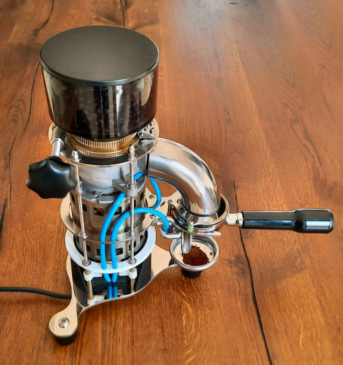
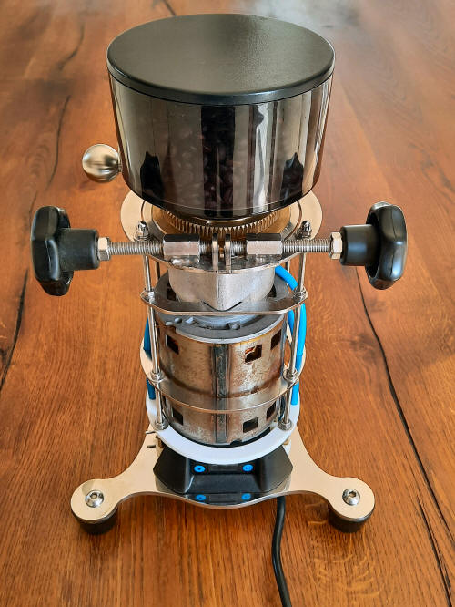
Finally the front, side and back view of the V2 grinder with the portafilter:
Play the video to see a resume of the coffee grinder key features. Feedbacks received from some US coffee forums:
|


