 |
|
|
CV | DESIGN | ART | AUDIO | CONTACT |
|
Mechanical Ventilation System
This project was born for two main reasons, the first is to fight against humidity problems in some points of my house, the second is to purify air circulates inside the house and then also to increase the Energetic House Class. Resuming: to improve life quality! The main problem is well defined and visible on the following picture
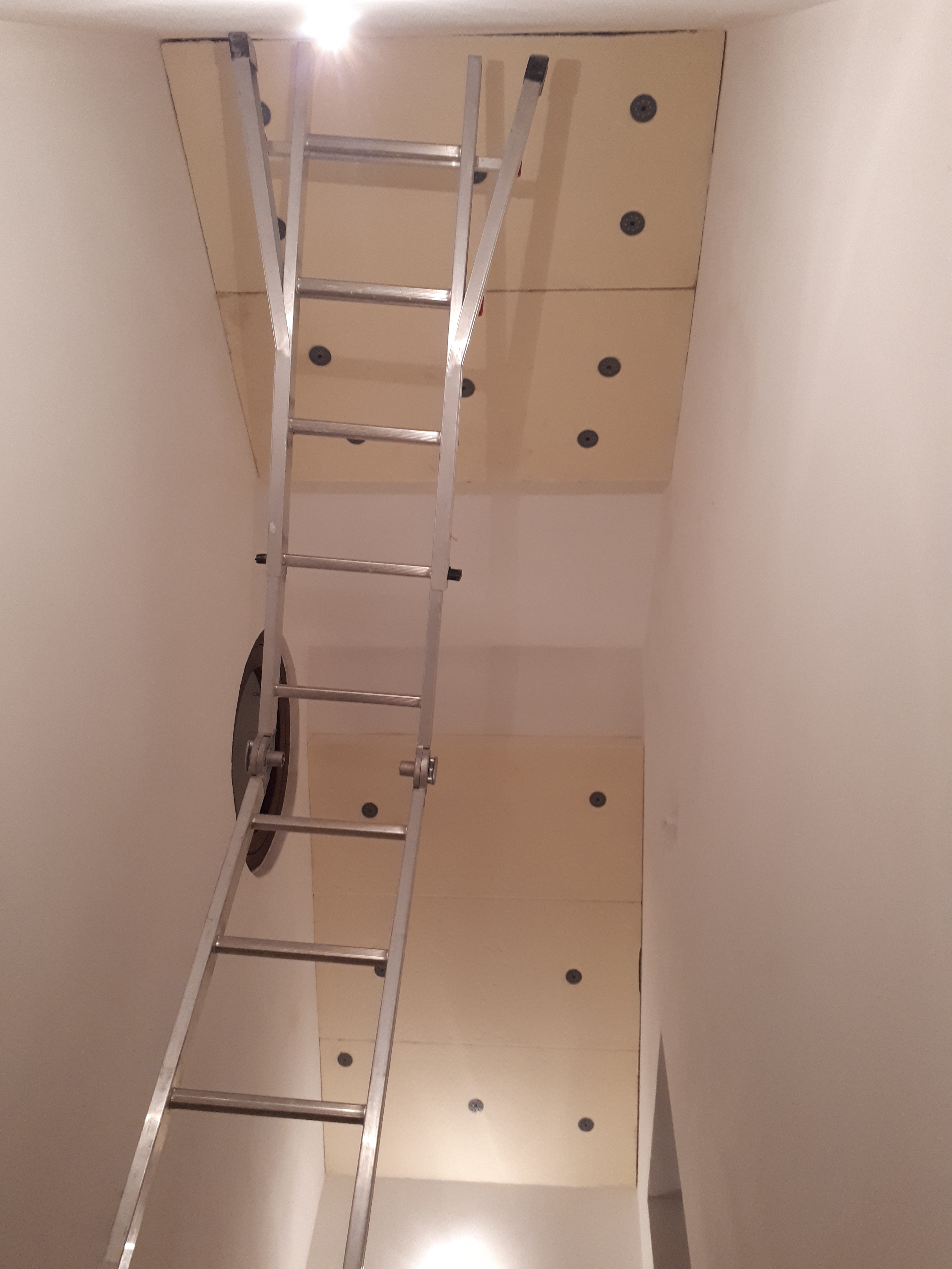
it is a bottom to top view of my house stairwell when I bought it, years ago. As we know, the air humidity starting to create condensation on cold surfaces when the temperature drop reach the dew point. Edges and corners -as usually- are the most delicates wall-roof junction points, created by the thermal bridges of standard construction methods, where the phenomenon became visible with mold spores.
In this picture is shown the original wooden porthole, for the new one follow the double insulated glazing project. The top side over the porthole was the point in which the condensation could be visible, the next zoom shows condensed water drops falling from the roof. This is the highest point of the building and as we can see it is a very big problem!
The issue is very simple to understand, because this section of the building is positioned on the north side, then for the original project of the building the used materials were not well selected considering carefully all correct thermal and humidity conditions (we have to take into account that the main section of this house dates back to first decades 1900, then a new section was added in the middle '80), moreover the environment conditions of this particular zone in Italy is subjected to a high average annual value of 76% RH, recorded from the Italian Air Force which drew up the following humidity map:
From which it's possible to see this is one of the areas with the highest humidity. The annual average changes, anyway it is one variable to consider for the project. These are fixed conditions I don't want to modify at the moment (for some of them I cannot, obviously), considering that increasing walls isolation will increase the problem, if it is used as unique solution. I don't want to consider other solutions as electric dehumidifiers, because these systems are noisy and not environmental awareness. I designed some passive dehumidifiers, but the calculated efficiency is not sufficient to solve this kind of problem, probably they will be subject of a next project description. So, the other conditions influencing condensation creation, which I can control perfectly, are inside the house: air flux and temperature distribution among the rooms. The project consists in a Centralised Mechanical Ventilation (CMV) system and it will be equipped also by a high efficiency Heat Recovery Ventilation (HRV). After indoor/outdoor temperature humidity measurements of concrete walls and rooms air (also theirs variations during seasons in strategic points of the building) I am ready to study the problem using a FEA thermo fluid dynamic non isothermal flow simulation. Designing the 3D structure adding only the bigger furnitures which can influence air fluxes or temperature conditions and selecting a detailed mesh, considering the involved physics and computational time
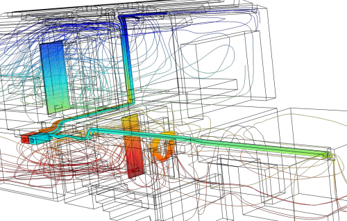
First of all it's possible to visualize the problem. In the bottom picture red isosurfaces represent heaters of the heating system, during operative condition on standard winter season, then delta difference between extreme temperatures indicates dark blue points are subjected to condensation phenomenon. On these surfaces air will be cooled, becoming saturated with water vapor, creating what is commonly called a "wet surface".
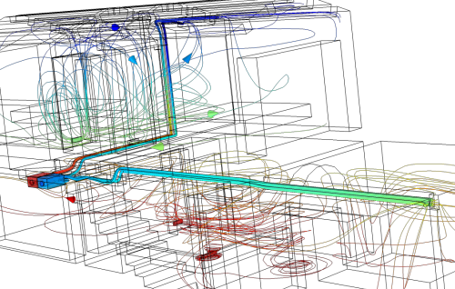
The next simulation shows the mechanical ventilation system, starting from the two plenums which distributing air through the pipes.
Colored streamlines represent the pressure range, these values are useful to evaluate the machine bahavior and define its technical data and the target performances for prevalence curves. Red color represents high pressure and blue color the low pressure, so the plenum in red is the fresh air inlet and the light blue plenum is exhaust air outlet. The top simulation is done with closed doors, the bottom one has some opened doors
Testing other setup conditions to modify pipes velocity and pressure inside rooms, in order to move air flux from downstairs to upstairs and finding the best solution for the air mixing
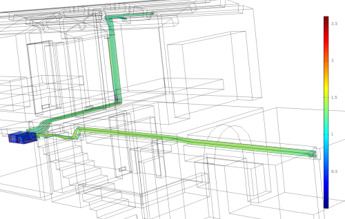
The next image represents the simulated air velocity inside pipes, it shows that at mid-high working conditions of the system power the air velocity at pipes exits is 2.5 m/s, it was my target for the noise reduction/volume velocity ratio.
The position of the system, pipes lenght/diameter and pipes inlets/outlets are variables to take into account for system performances and maintaining the target efficiency. I calculated the system without the need to use inlet or outlet pipe vents, in order to reduce all fluid resistances maximizing efficiency performances. Thus air speed, volume flow rate values, pipe number/lenght/diameter for each room and total system power is already calibrated by the project and it is not necessary to calibrate fluxes in situ after the installation. I followed UNI EN 15251, UNI EN 13779 and UNI EN 15242 for the correct air volume exchange to reach the best result, then considering leakages the system works always in a low pressure closed loop. Ok, now we can take action! The first step is the indoor roof isolation with a layer of xps. Selecting xps with a low deformation on temperature variation ≤5% (@40 kPa - 70 °C) and a good dimensional stability on absorbing water ≤4% (@70 °C - 90 %RH). The other material characteristics are not important.
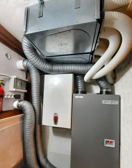
The xps layer as predicted reduces about 24% of the air condensation on the stairwell roof, but this step was necessary, because it will work in combination with the ventilation system. In the next picture there is the equipment department with the main system, plenums and pipes.
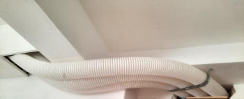
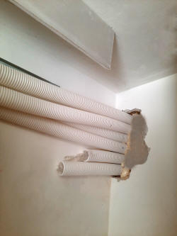
then working on pipes installation and drywalls
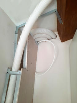
finding some solutions to hide pipes at the same time permitting a good air exchange inside the rooms
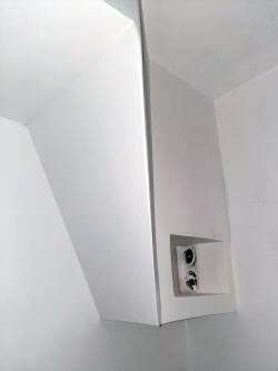
For hiding two pipes and mainly to hide their two vents inlet
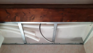
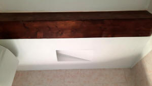
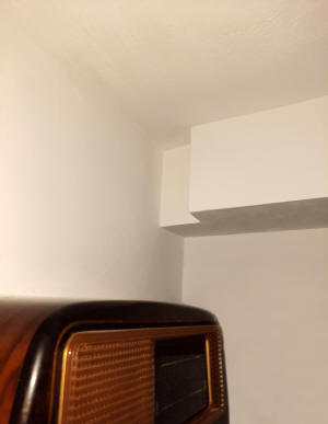
I designed the solution of a broken beam in a blind corner, as the following picture:
with this solution I have the lowest fluid dynamic losses in this room, compared to the total flux optimization for the air exchange.
Condensation and humidity problems are 100% solved as shown in the final pictures here: double insulated glazing project. The humidity average value is now set @54% RH with very low oscillations in the coldest winter season, considering that in the same conditions, before this project, I measured peaks more than 80% during cooking or showering.
|


